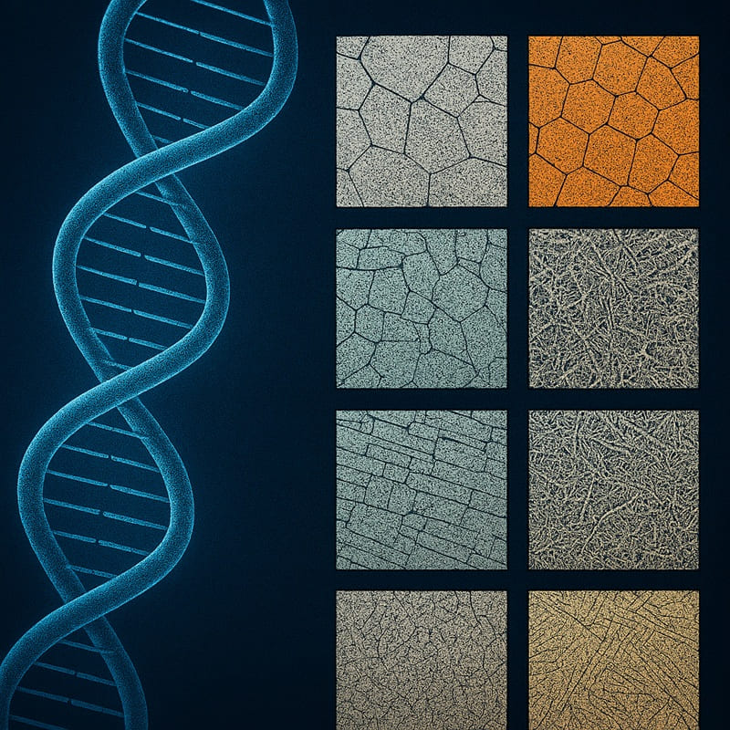
In the fascinating realm of materials science, metallographic structures serve as the foundational blueprint for understanding metals, much like DNA maps out the essence of life. Imagine metals not as inert substances but as dynamic entities whose “genetic code” dictates their strength, flexibility, and resilience. This article delves into the “DNA Map of the Metal World,” decoding 14 key metallographic structures that form the microscopic architecture of metals. These structures are the hidden patterns revealed under a microscope, influencing everything from the durability of a skyscraper’s steel beams to the precision of aerospace components.
The analogy to DNA is apt because just as genetic sequences determine an organism’s traits, metallographic structures—formed by the arrangement of atoms, grains, and phases—govern a metal’s mechanical, thermal, and chemical properties. For engineers and scientists, mastering these structures is akin to unlocking a genetic code, enabling the design of superior materials.
At Heeger Metal, we specialize in high-quality refractory metal products with a variety of materials, forms, and specifications, ensuring optimal performance for industrial and scientific applications.
What Are Metallographic Structures?
Metallographic structures refer to the intricate microscopic arrangements within metals and alloys, visible only after careful preparation and examination under a microscope. These structures encompass the size, shape, and distribution of grains (crystalline regions), phases (distinct chemical compositions), and defects (such as dislocations or inclusions). They emerge from the solidification, deformation, or heat treatment processes that metals undergo, transforming a molten mass into a functional material.
The importance of these structures cannot be overstated; they directly influence a metal’s properties. For instance, a fine-grained structure might enhance toughness and resistance to cracking, while a coarse one could improve machinability but reduce strength. In practical terms, understanding metallographic structures allows engineers to predict how a metal will behave under stress, corrosion, or high temperatures—critical for applications in industries like automotive, construction, and electronics.
To reinforce the DNA metaphor, think of metallographic structures as the “genetic code” embedded in metals. Just as DNA strands code for proteins that build living tissues, these structures encode the “instructions” for a metal’s performance. Alterations—through processes like annealing or quenching—can “rewrite” this code, much like gene editing. This analogy highlights the precision required in metallurgy: a small change in cooling rate can shift a structure from ductile to brittle, with profound implications.
Key Components of Metallographic Structures:
- Grains: Polygonal crystals formed during solidification; their boundaries affect strength.
- Phases: Homogeneous regions with uniform composition, like alpha or beta in alloys.
- Defects: Imperfections such as voids or impurities that can either weaken or strengthen the material.
The 14 Key Metallographic Structures
The field of metallography is defined by a number of critical microstructures that dictate the properties and performance of metals and alloys.
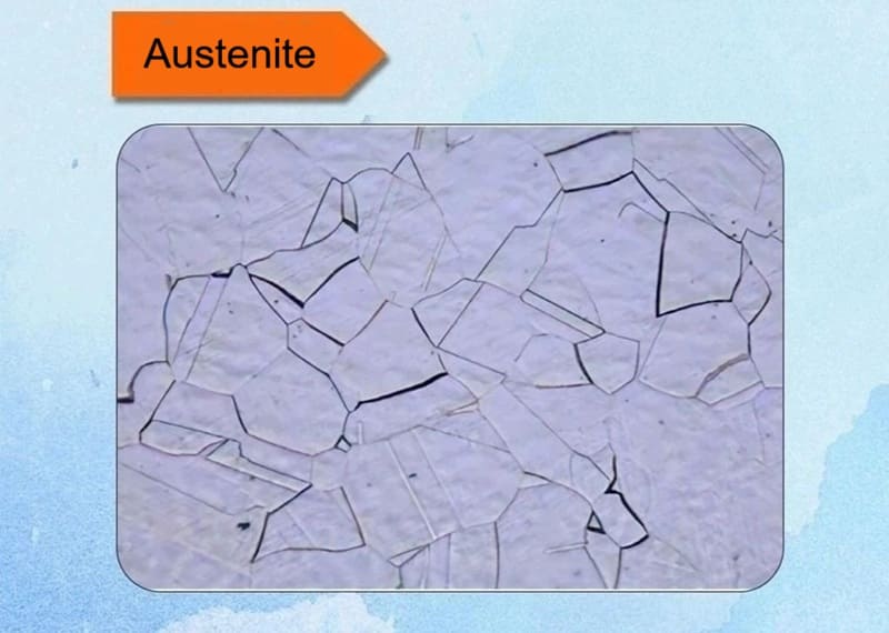
1. Austenite
This face-centered cubic phase is stable at high temperatures (above 912°C in iron) and is non-magnetic. In stainless steels, chromium and nickel extend its stability to room temperature. It features equiaxed grains and high solubility for carbon. Formed by heating, it enables hot working. Austenite offers superior corrosion resistance and formability, used in kitchen utensils and medical implants, though it can be prone to work hardening.
Key Characteristics:
- Crystal Structure: Face-Centered Cubic (FCC). This structure has an atom at each corner of the cube and one at the center of each face. The FCC lattice is more “open” than other iron structures, allowing carbon atoms to dissolve interstitially (in the spaces between iron atoms) with relative ease.
- Carbon Solubility: Austenite has the highest solubility for carbon of all the iron phases. It can dissolve up to ~2.1% carbon by weight at 1147°C (2097°F). This high carbon content is crucial for heat treatment.
- Non-Magnetic: It is typically non-magnetic, which is a simple way to distinguish it from the magnetic ferrite phase.
- Stability: It is only stable at high temperatures (under equilibrium conditions). For a typical plain-carbon steel, austenite exists between 727°C (1341°F) and 1495°C (2723°F). This temperature range is defined on the Iron-Carbon Phase Diagram.
Formation and Role in Heat Treatment:
Austenite is not a room-temperature phase in most steels, but it is the starting point for almost all heat treatments. The process is as follows:
- Heating (Austenitizing): The steel is heated above its upper critical temperature (the A₃ or Acm line on the phase diagram), transforming its room-temperature microstructure (usually ferrite and cementite) entirely into austenite.
- Soaking: It is held at that temperature to achieve a uniform chemical composition and temperature throughout the piece.
- Cooling (Quenching/Tempering): The steel is then cooled at a specific, controlled rate. The way this austenite transforms upon cooling determines the final properties of the steel (hardness, strength, toughness). This is the most critical step.
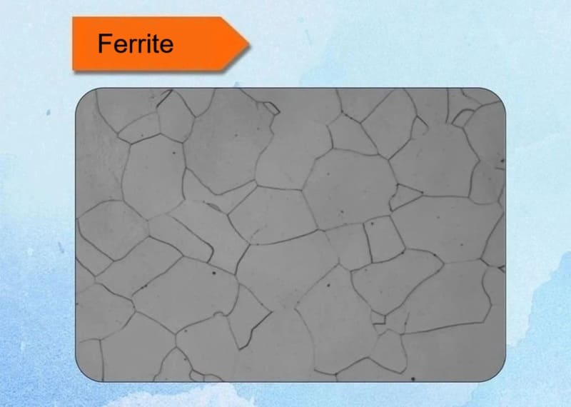
2. Ferrite
Ferrite, also known as alpha-iron, is a soft, magnetic phase with a body-centered cubic crystal structure. It forms in low-carbon steels during slow cooling from austenite. Microscopically, it appears as polygonal grains with low hardness. Formation requires temperatures below 912°C in pure iron, but alloying elements like silicon stabilize it. Properties include excellent ductility and weldability, making it ideal for automotive body panels. However, its low strength limits use in high-load applications.
Key Characteristics:
- Crystal Structure: Body-Centered Cubic (BCC). This structure has an atom at each corner of the cube and one in the very center of the cube. The interstitial spaces in the BCC lattice are smaller than in the FCC structure of austenite.
- Carbon Solubility: Ferrite has a very low solubility for carbon. It can dissolve a maximum of only 0.022% carbon by weight at 727°C (1341°F). At room temperature, its solubility drops to almost nil (~0.005%). This extremely low carbon content is the primary reason for its softness and lack of hardness.
- Magnetic: Ferrite is strongly magnetic. In fact, it is the phase responsible for the magnetism in plain carbon steels at room temperature.
- Stability: It is the stable phase of pure iron at room temperature and is a primary constituent of most low-carbon steels under equilibrium conditions.
Properties:
Due to its very low carbon content, ferrite exhibits a specific set of mechanical properties:
- Soft: Very low hardness and strength.
- Ductile and Malleable: Exhibits high elongation, meaning it can undergo significant plastic deformation without fracturing. This makes it easy to form and shape.
- Tough: Has good impact resistance at room temperature.
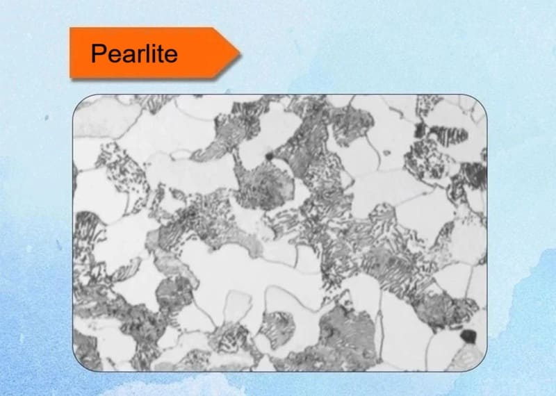
3. Pearlite
This lamellar structure consists of alternating layers of ferrite and cementite, resembling a pearl under magnification. It forms via eutectoid transformation at around 727°C in carbon steels. The fineness depends on cooling rate—slower cooling yields coarser pearlite. It balances strength and ductility, commonly found in rails and wires.
Key Characteristics:
- Composition: A fine, alternating mixture of soft, ductile ferrite (α-iron) and hard, brittle cementite (iron carbide, Fe₃C).
- Formation: It is the product of the eutectoid reaction that occurs at 727°C (1341°F) in the iron-carbon system under equilibrium conditions. The reaction is:
Austenite (0.76% C) ⇨ Ferrite (0.022% C) + Cementite (6.67% C) - Lamellar Structure: The two phases form in parallel plates or lamellae. This structure is a result of the need to minimize energy during the transformation; the layered formation reduces strain energy at the boundaries between the phases.
4. Cementite
A brittle iron carbide (Fe3C) with an orthorhombic structure, appearing as white, hard particles. Forms in high-carbon alloys during solidification. Enhances hardness but reduces ductility; key in tool steels for abrasion resistance.
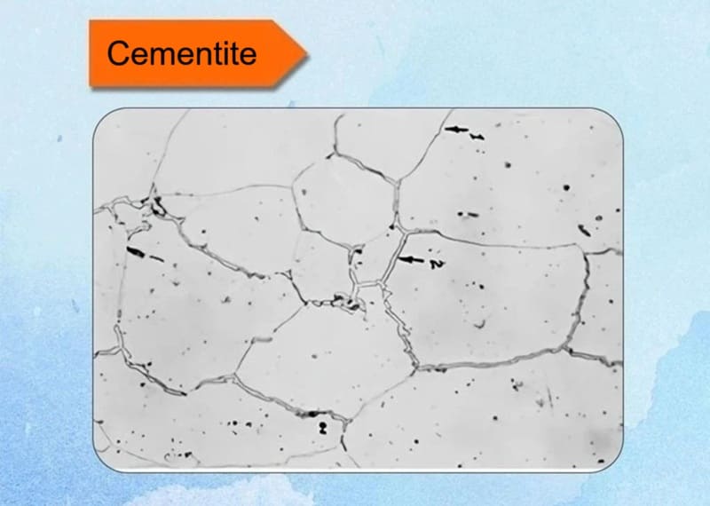
Key Characteristics:
- Composition: It is a compound, not a solid solution. Its composition is fixed at 6.67% carbon and 93.33% iron by weight. This is in stark contrast to phases like austenite and ferrite, which are solid solutions with variable carbon content.
- Crystal Structure: It has an orthorhombic crystal structure, which is complex and highly asymmetric. This structure contributes significantly to its extreme hardness and brittleness.
- Stability: Cementite is metastable. This means it is not truly stable but decomposes very slowly (over many years) into iron and carbon (graphite). This decomposition is a concern in cast irons but is negligible in most steels.
- Hardness: It is extremely hard (~800-1200 HV) and very brittle. It is one of the hardest phases found in standard ferrous alloys.
- Magnetism: It is magnetic up to its Curie temperature of approximately 215°C (419°F), after which it becomes non-magnetic.
5. Widmanstätten Structure
Characterized by coarse, plate-like ferrite precipitating from austenite boundaries, often in overheated steels. Forms during slow cooling from high temperatures. Reduces impact toughness; seen in welds, requiring normalization to refine.
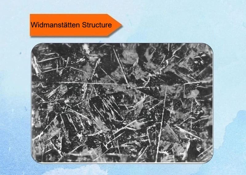
Key Characteristics:
✅Appearance: It appears as a network of sharp, crystallographically oriented plates or needles. In steels, these are typically plates of ferrite or cementite.
✅Formation Mechanism: It forms through a diffusional, displacive transformation but with specific conditions:
- Medium Cooling Rate: It forms at a cooling rate that is too fast to allow for equilibrium structures (like polygonal ferrite) but too slow to form martensite.
- Nucleation and Growth: The new phase (e.g., ferrite) nucleates preferentially at the austenite grain boundaries.
- Oriented Growth: Instead of growing as equiaxed grains, it grows in specific crystallographic planes of the parent austenite grain where there is a good atomic match (low interfacial energy). This leads to the acicular (needle-like) or plate-like morphology.
✅Conditions for Formation:
- High Austenitizing Temperature: A high heating temperature creates coarse austenite grains. Large grains provide a long, uninterrupted path for the plates to grow, making the pattern more pronounced.
- Specific Alloy Composition: Steels with specific alloying elements are more prone to it.
- Critical Cooling Rate: The cooling rate must be within a specific window to promote this type of growth.
6. Ledeburite
A eutectic mixture of austenite and cementite in cast irons, appearing as a mottled structure. Forms at 1147°C in hypereutectic irons. Provides extreme hardness for wear parts like mill rolls.
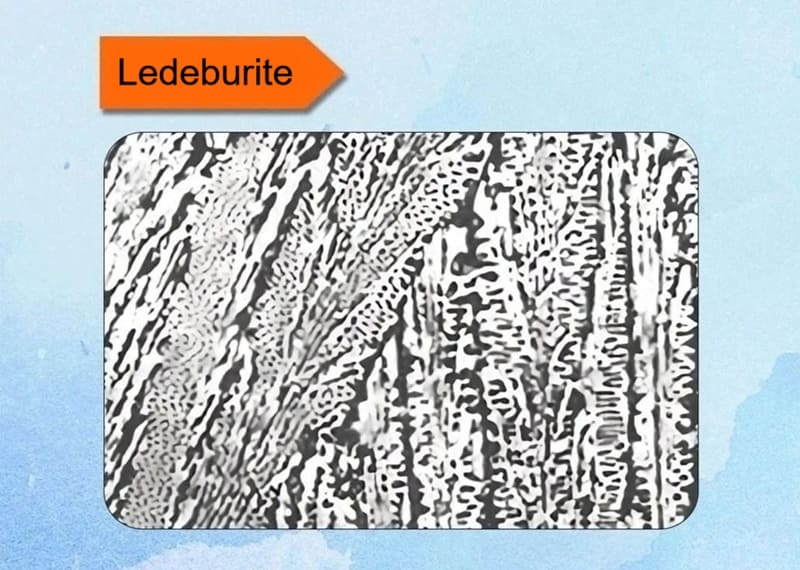
Key Characteristics:
- Definition: Ledeburite is a eutectic mixture of austenite and cementite. A eutectic mixture is a two-phase structure that solidifies at a specific composition and temperature from a liquid solution.
- Composition: It forms at the fixed carbon composition of 4.3% by weight.
- Formation Temperature: It solidifies at a constant temperature of 1147°C (2097°F) via the eutectic reaction:
Liquid (4.3% C) ⇨ Austenite (2.11% C) + Cementite (Fe₃C) - Appearance: Under a microscope, it typically has a characteristic “Chinese script” or rosette-like pattern, where the cementite forms a continuous background with islands or globules of austenite (which later transforms into other structures upon cooling).
7. Upper Bainite
Upper bainite is one of the two main forms of bainite, a microstructure that forms in steel during the continuous cooling or isothermal transformation of austenite at temperatures between those which produce pearlite and those which produce martensite. It forms at the higher end of the bainitic temperature range.
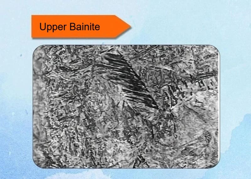
Key Characteristics:
✅Formation Temperature Range: Typically forms between approximately 350°C and 550°C (662°F – 1022°F). This is the “upper” part of the bainite transformation range.
✅Mechanism: It forms through a diffusional-displacive transformation. While it shares some characteristics with a diffusion-controlled reaction (like pearlite), carbon diffusion is limited and cannot occur over long distances. The iron atoms move in a coordinated, shear-like manner, similar to martensite, but much slower.
✅Microstructure: The classic microstructure of upper bainite consists of:
- Laths or Platelets of Ferrite: These are the main body of the structure.
- Cementite Precipitates: Cementite (Fe₃C) particles precipitate between the ferrite laths or at the ferrite lath boundaries. This is a key distinguishing feature from lower bainite.
- The overall structure under a microscope often appears as feathery or as bundles of parallel laths.
8. Lower Bainite
Lower bainite is the second main form of bainite, forming at the lower end of the bainitic temperature range. It is generally considered more desirable than upper bainite for applications requiring a good combination of strength and toughness.
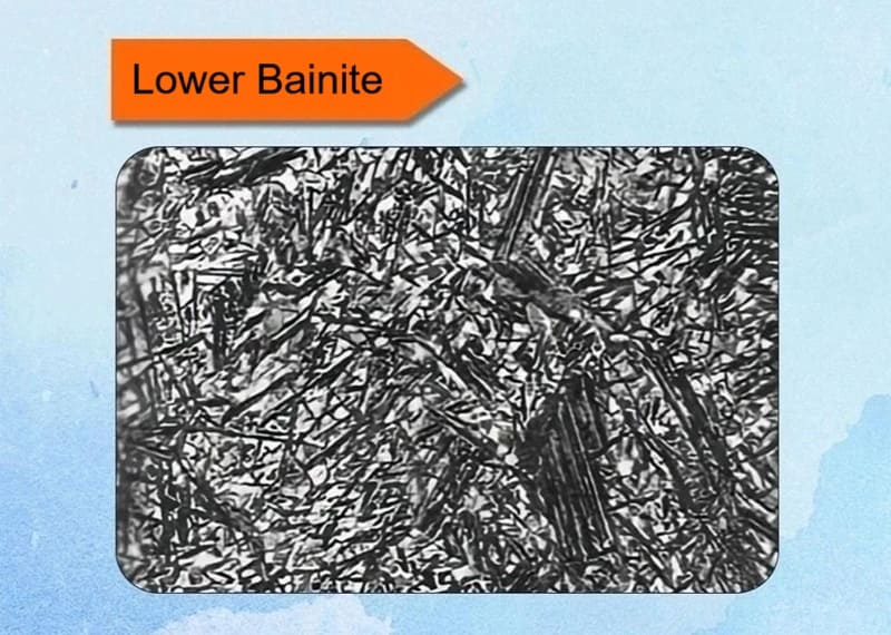
Key Characteristics:
✅Formation Temperature Range: Typically forms between approximately 250°C and 350°C (482°F – 662°F). This is the “lower,” cooler part of the bainite transformation range.
✅Mechanism: Like upper bainite, it forms through a diffusional-displacive transformation. However, because the transformation occurs at a lower temperature, the diffusion of carbon atoms is significantly more restricted.
✅Microstructure: The classic microstructure of lower bainite consists of:
- Plate-like units of Ferrite: These appear more acicular (needle-like) or plate-like compared to the lathy structure of upper bainite.
- Fine Carbide Precipitates: The defining feature is the presence of very fine carbide particles precipitated inside the ferrite plates. This is a key distinction from upper bainite. The carbides are often oriented at a ~55-60° angle to the long axis of the ferrite plate.
9. Granular Bainite
Granular bainite is a distinct bainitic microstructure that typically forms in low-carbon and low-alloy steels during continuous cooling (e.g., air cooling or controlled rolling), often at cooling rates slightly slower than those that produce upper bainite. It is characterized by its unique morphological appearance rather than a specific transformation mechanism.
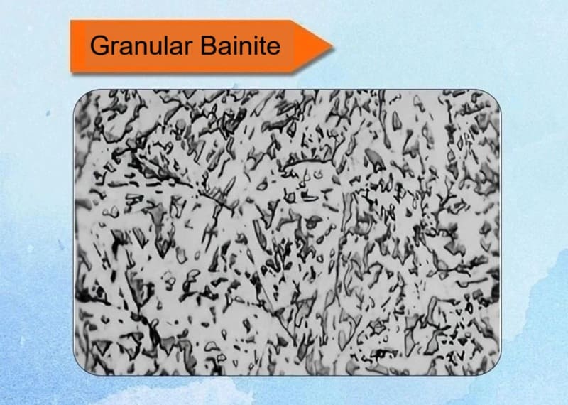
Key Characteristics:
✅Microstructure: The name “granular” comes from its appearance under a light microscope. It consists of:
Irregular, island-like constituents (the “granules”) dispersed in a matrix of featureless ferrite. These islands are often called MA Constituents (Martensite-Austenite Constituents).
✅Formation: It forms in a specific temperature range, often overlapping with or just below the upper bainite range, during continuous cooling. It is very common in the heat-affected zone (HAZ) of welds and in thermomechanically controlled processed (TMCP) steels.
✅Transformation Process:
- Blocks of unstable, carbon-rich austenite are surrounded by a matrix of bainitic ferrite.
- Upon further cooling, these carbon-enriched austenite regions transform into a mixture of martensite and retained austenite (MA constituents). They do not have time to decompose into ferrite and carbide like in classical bainite.
10. Spheroidized Bainite
Spheroidized bainite is a specific and desirable form of bainite where the cementite (Fe₃C), instead of forming as continuous films or fine needles, is present as small, dispersed, spheroidal particles within a ferrite matrix. It is not a distinct phase but rather a specific morphological state of bainite that offers a superior combination of properties.
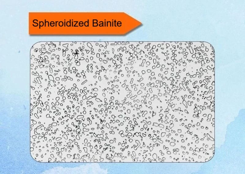
Key Characteristics:
✅Microstructure: The defining feature is the spheroidized cementite particles. Unlike the lamellar structure of pearlite or the interlath carbides of upper bainite, the carbides in this structure are small, rounded, and globular.
✅Formation Mechanism: It is typically not formed directly from austenite. Instead, it is achieved through a specific heat treatment process applied to existing bainitic or martensitic structures:
- Austempering with Extended Holding: The steel is transformed isothermally in the bainitic region (austempering), but the holding time at temperature is significantly extended.
- Tempering of Bainite: A more common industrial method is to take steel with a bainitic (or even martensitic) microstructure and subject it to a prolonged tempering treatment at a temperature below the lower critical temperature (A₁), typically between 600°C and 700°C (1112°F – 1292°F). This process is called spheroidize annealing or spheroidizing.
✅Driving Force: The driving force is the reduction of interfacial energy. The total surface area of many small spheres is much less than the surface area of long, thin plates or needles. Over time, the carbide morphology changes to this more thermodynamically stable, lower-energy state.
11. Martensite
A hard, needle-like structure formed by rapid quenching of austenite, distorting the lattice into a tetragonal form. It appears as acicular (needle-shaped) plates under the microscope. Requires high cooling rates to prevent diffusion. Martensite is exceptionally hard but brittle, perfect for cutting tools and gears after tempering to reduce brittleness.
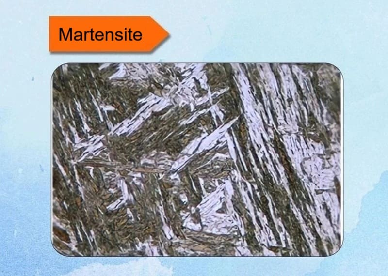
Key Characteristics:
- Formation Mechanism: Diffusionless Transformation. This is the most critical concept. When austenite is cooled rapidly enough (quenched), carbon atoms do not have time to diffuse out of the crystal lattice to form cementite (Fe₃C). Instead, the FCC austenite structure undergoes a rapid, shear-like transformation where the iron atoms realign themselves into a Body-Centered Tetragonal (BCT) structure, trapping the carbon atoms in place.
- Crystal Structure: Body-Centered Tetragonal (BCT). This is similar to a Body-Centered Cubic (BCC) structure but stretched along one axis (the ‘c’ axis) due to the trapped carbon atoms. The degree of tetragonality (the c/a ratio) is directly proportional to the carbon content. Pure iron (0% carbon) forms BCC martensite, but any amount of carbon results in a BCT structure.
- Carbon Content: Martensite has the exact same carbon content as the parent austenite from which it formed. This supersaturated solid solution of carbon in iron is the root cause of its extreme hardness.
- Microstructure: It has an acicular (needle-like) or lath-like appearance under a microscope. High-carbon martensite looks like fine, intersecting needles, while low-carbon martensite has a more lath-like or plate-like structure.
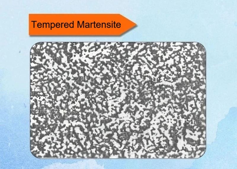
12. Tempered Martensite
Tempered martensite is the microstructure resulting from the heat treatment of as-quenched martensite. While martensite provides extreme hardness, it is too brittle for most applications. Tempering is the essential process that transforms this brittle structure into a tough, usable, and engineered material.
Key Characteristics:
✅Definition: It is the microstructure of martensite that has been reheated to a temperature below the A₁ line (727°C / 1341°F) to allow for controlled precipitation and stress relief.
✅Process: Tempering. This involves a three-stage process where the unstable, supersaturated martensite decomposes into a more stable mixture:
- Stage 1 (Up to ~200°C): Carbon atoms cluster and precipitate as a transition carbide called epsilon-carbide (ε-carbide). The matrix remains tetragonal but has a lower carbon content. This stage reduces internal stresses slightly.
- Stage 2 (~200-300°C): Any retained austenite (if present) decomposes into lower bainite.
- Stage 3 (~300-700°C): The epsilon-carbide and low-carbon martensite decompose into the stable phases of ferrite (α-iron) and cementite (Fe₃C). The cementite particles initially form as very fine, needle-like precipitates and then coarsen and spheroidize into small, rounded particles as the tempering temperature and time increase.
✅Microstructure: The final structure is a matrix of fine ferrite with a uniform dispersion of fine cementite particles. The acicular (needle-like) morphology of the original martensite is often still visible.
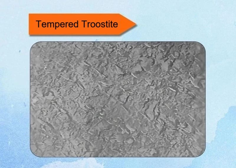
13. Tempered Troostite
Tempered troostite is a microstructure formed during medium-temperature tempering (350-500°C) of quenched steel. It is a mixture of ferrite and very fine cementite. The overall appearance is uniformly dark, and its properties lie between those of tempered martensite and sorbite.
Key Characteristics (Historical Context):
✅Formation: It was defined as the structure obtained by tempering martensite in the range of approximately 400°C to 500°C (750°F to 930°F).
✅Microstructure: Under the light microscopes available at the time, tempered troostite appeared as a dark-etching, poorly resolved matrix. We now understand this microstructure to consist of:
- A ferrite matrix that has largely lost the tetragonality of martensite.
- Very fine, needle-like or rod-like cementite (Fe₃C) particles precipitated within that matrix. These particles are too fine to be resolved with a light microscope, causing the dark, featureless appearance.
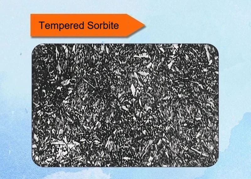
14. Tempered Sorbite
The product of high-temperature tempering (500-650°C) consists of polygonal ferrite grains and uniformly distributed fine particulate cementite. The structure is dense and appears grayish-black, with boundaries that are not easily discernible.
Key Characteristics:
✅Formation: It was defined as the structure obtained by tempering martensite at temperatures of approximately 500°C to 650°C (930°F to 1200°F)—the higher end of the tempering spectrum.
✅Microstructure: Under a light microscope, it appeared as a dark matrix with clearly visible, speckled white particles. We now know this structure consists of:
- A fully recovered, equiaxed ferrite matrix.
- Coarse, spheroidized cementite (Fe₃C) particles evenly dispersed throughout the matrix. The carbides are large enough to be resolved with a light microscope, creating the characteristic “speckled” appearance.
The Role of Metallographic Structures in Material Design
Metallographic structures—the microscopic arrangement of grains, phases, and defects within a metal or alloy—are the fundamental link between a material’s processing history and its final properties. In material design, understanding and controlling these structures is not just important; it is the very essence of the field. The central paradigm of physical metallurgy is:
Processing → Structure → Properties → Performance
This means that how you make and treat a material (processing) determines its internal architecture (structure), which dictates its measurable characteristics (properties), and ultimately defines how well it performs in a real-world application (performance).
Understanding metallographic structures is pivotal in engineering tailored materials. By manipulating these through alloying and processing, designers can optimize for specific needs, such as high-strength steels for bridges or lightweight alloys for aircraft.
Heat treatment processes like quenching (rapid cooling for martensite) or annealing (slow cooling for spheroidite) directly alter structures, enhancing properties. For example, tempering martensite reduces brittleness while retaining hardness.
Benefits in Design:
- Customization: Match structures to environments (e.g., austenite for corrosion).
- Sustainability: Refine structures to extend material life, reducing waste.
In conclusion, the 14 key metallographic structures serve as the blueprint of metals, shaping their properties and performance in ways that drive technological advancement. From enhancing the strength of alloys to improving the efficiency of energy systems, these microscopic structures are fundamental to innovations across industries. As we decode more of these intricate patterns, the potential for developing smarter, more sustainable materials becomes limitless. The future of metallurgy holds the promise of breakthroughs that will continue to transform our world.
For top-quality refractory metal products, Heege Metal provides tailored solutions and precision machining techniques for various applications.
Looking for premium refractory metal products? Contact us today!